
For a client in Northern Europe, Studio Spizuoco Ingegneria carried out the stress analysis of several circuits connected to an LPG storage tank. The load line presented here is the most instructive of them: in a short length of pipe it combines almost every effect that makes tank piping demanding, and several of those effects call for opposite design choices.
- Scope
- Stress analysis of the piping circuits of an LPG storage tank
- Code
- EN 13480-3 (metallic industrial piping)
- Software
- Hexagon CAESAR II, as specified by the client
- Operating temperature
- −30 °C
- Key issues
- Tank settlement, roof contraction, flashing-induced vibration, unreinforced branch connections
Tank settlement: permanent and elastic components
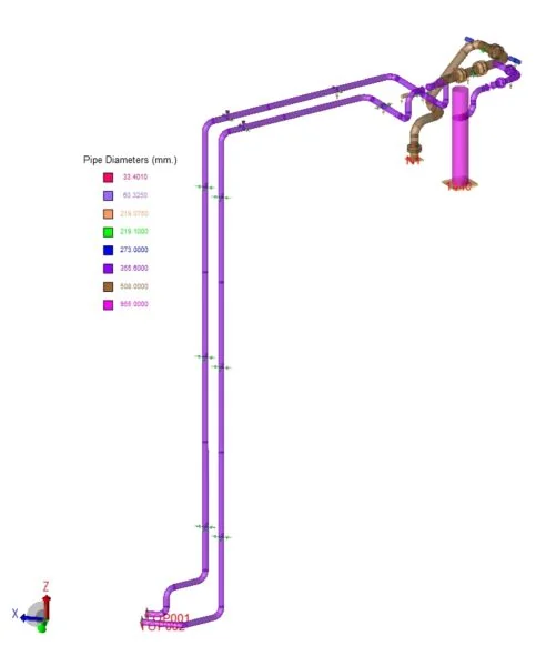
As for any storage tank, the settlement of the foundation must be imposed on the connected piping. The difficulty lies in the data. A settlement value on a vendor drawing does not say how much of it is a permanent sinking of the foundation and how much is an elastic deflection that follows the filling level. The two enter the analysis differently: the permanent part is a single, non-repeated movement, which EN 13480-3 checks with its own stress criterion; the elastic part comes and goes with every filling cycle and therefore belongs to the cyclic, displacement-driven stress range.
The split was agreed with the tank manufacturer before the load cases were finalised. That discussion is a small investment: assuming the whole settlement to be cyclic penalises the design, while assuming it to be permanent can hide a fatigue problem.
Thermal contraction of the tank and its roof
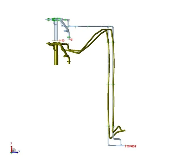
At −30 °C the tank shell contracts radially and the roof structure contracts with it. The pipe supports fixed to the roof are carried along, so the piping does not see a single imposed movement but the superposition of three: thermal contraction, foundation settlement and the deflection of the roof structure under load. Each was calculated or obtained from the vendor and imposed at the relevant supports and at the tank nozzle, consistently with the operating condition being analysed.
The practical consequence is that the first supports on the roof cannot be treated as fixed points in space. Treating them as such would underestimate the loads on the nozzle and the stresses at the first elbows.
Vibration from flashing downstream of the control valve
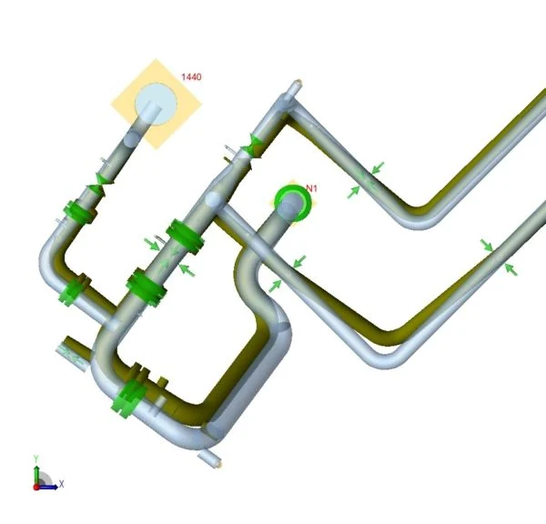
Between the flow control valve and the tank nozzle the pressure drops and the liquid can partially flash, producing a two-phase flow that excites the piping. The line was therefore assessed with the Energy Institute Guidelines for the Avoidance of Vibration Induced Fatigue Failure in Process Pipework, which provide a screening method for this mechanism and for the small-bore connections most exposed to it.
Here the design problem becomes a genuine trade-off. Vibration calls for a stiff line with high natural frequencies; thermal contraction and settlement call for flexibility. The support arrangement was developed to restrain the lateral directions in which vibration acts while leaving the line free to follow the thermal and settlement movements — and every support was checked to be buildable on the roof structure. Where a multiphase process study is available, the flow regime can be quantified and the excitation forces used in a dynamic analysis; in this project the screening approach was sufficient.
An unreinforced branch with a high SIF
The piping specification called for unreinforced pipe-to-pipe branch connections, combined with a thin header wall. For this kind of fitting the stress intensification factor grows rapidly as the header thickness decreases, and values close to 10 were reached. At that level the branch, not the bends, governs the line: a moderate bending moment is enough to exceed the allowable range.
Connections of this type deserve explicit discussion with the client. The options are a reinforced or contoured fitting, a heavier header, or a support layout that keeps the moments at the branch low. The analysis must make the issue visible, so that the decision is taken at the right level rather than buried in a stress table.
Key points for LPG and cryogenic tank piping
- Agree the permanent and elastic parts of the settlement with the tank vendor before defining load cases.
- Roof-mounted supports move: impose contraction, settlement and roof deflection together.
- Downstream of control valves, screen for flashing-induced vibration and restrain only the directions that need it.
- Check the SIF of unreinforced branches early; with thin headers it can govern the whole line.
Outcome
The result was a support layout that is stiff where vibration requires it and flexible where contraction and settlement require it, practical to build on the roof structure, and documented in a report that the client could verify point by point. The same approach applies to other software and codes: the studio also works with Bentley AutoPIPE and to ASME B31.3.