When the ground under a pipeline settles unevenly, the pipe does not translate as a whole. It bends, passes part of the load to the soil through its supports and develops bending moments, shear and, if the deformation is large, axial tension. The shape of the settlement therefore matters at least as much as its amplitude. Here I explain how PLE (ex Ple4Win) describes it, which formulas follow and how I used it on a real, anonymised project.
- Software
- PLE (ex Ple4Win)
- Load
- Vertical ground subsidence, SUBSIDE table
- Case data
- Two settlements: 10 mm over a 44.7 m half wave (Double) and 5 mm over 8.8 m (Right), UNCF 1.5
- References
- NEN 3650-1 and NEN 3650-2
PLE and the SUBSIDE table
PLE (ex Ple4Win) is a pipe stress analysis program with a strong specialisation in pipelines and buried piping; according to the vendor it can model above-ground and buried sections in the same model. Vertical ground settlement is assigned in the SUBSIDE table, which does not impose a displacement at a node but a profile along the line, defined by four inputs:
- SUBZMAX: maximum settlement in the z direction, negative downwards;
- UNCF: uncertainty factor (≥ 1, default 1.5); SUBZMAX is always multiplied by UNCF;
- LENGTH: length over which the settlement goes from zero to its maximum, equal to half a sine wavelength;
- SINESHAPE: profile shape. Double is a half wave on both sides of the reference point X-P; Left and Right are a half wave on one side only, with zero settlement on the other; Block is a step from zero to SUBZMAX at X-P, constant over LENGTH.
In every sinusoidal case the maximum is at X-P.
The model: a beam on elastic soil
The affected length of pipe is described as a beam on distributed springs of stiffness k per unit length, whose lower ends follow the ground settlement s(x) (Winkler model):
where EI is the bending stiffness and q(x) the distributed load on the pipe (self-weight and contents). The characteristic length is 1/λ, with
A sinusoidal profile of wavenumber ω is followed by the pipe only in part:
For a half wave of length ℓ, ω = π/ℓ. If ℓ is large compared with 1/λ the pipe follows the ground; if it is small, the pipe bridges the settlement and its strains are lower than the ground's. In practice the springs have a limit (passive pressure, bearing capacity) and the problem is not linear: the formula is a guide, not a substitute for the calculation.
What the standard says
NEN 3650-1:2020, Annex C.4.1.2, treats the pipeline as a beam under differential settlement. The settlement load Qz is not transferred to the soil through moments or tangential stresses on the wall, but through the lateral support zones, where the reaction is limited by the bearing capacity; where the pipe does not follow the settlement, the reaction is limited by the passive pressure. The upper limit of the load is
that is, passive pressure plus the weight of pipe and contents. The result is bending moments, shear and, depending on the deformation, axial tension from catenary action. For ring interaction (C.4.1.3) and for highly compressible soils, with heave and squeezing, refer to the standard.
Imposed displacement or sinusoidal profile
Imposing a displacement at a few nodes concentrates the rotation at those points, while the length between nodes stays straight. The PLE profile instead distributes the curvature along the half wave. With a = |SUBZMAX|·UNCF and ℓ = LENGTH, in the Double shape the settlement at distance s from X-P is
for |s| ≤ ℓ and zero elsewhere; in the Right and Left shapes the same expression applies on one side only. The maximum curvature and, for a pipe of outside diameter D that follows the ground completely (hence an upper bound), the bending strain are
Curvature grows with 1/ℓ², while amplitude enters only linearly. In the Right and Left shapes there is also a displacement jump equal to a at X-P: it is not curvature but a differential that the pipe absorbs over a length set by the soil interaction, not by LENGTH. That is where the results deserve the closest reading.
My experience on a project
On a project with a buried pipeline I applied the subsidence starting from the buried valve, towards the outside of the plant. In the SUBSIDE table (figure 3) I defined two settlements: sub1, SUBZMAX = −10 mm, LENGTH = 44.7 m, shape Double; sub2, SUBZMAX = −5 mm, LENGTH = 8.8 m, shape Right. With UNCF = 1.5 the applied settlements are 15 mm and 7.5 mm.
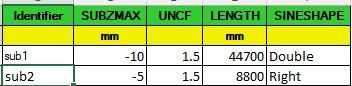
The numbers say more than they seem to. Since LENGTH is half a wavelength, sub1 is a bowl 89.4 m long, with a maximum curvature of about 3.7·10−5 m−1 (radius of about 27 km). sub2 has half the amplitude but a length five times shorter: the curvature rises to about 4.8·10−4 m−1 (radius of about 2.1 km), 13 times that of sub1. In terms of curvature the small, short zone is the more severe one, and the jump at X-P typical of the Right shape comes on top.
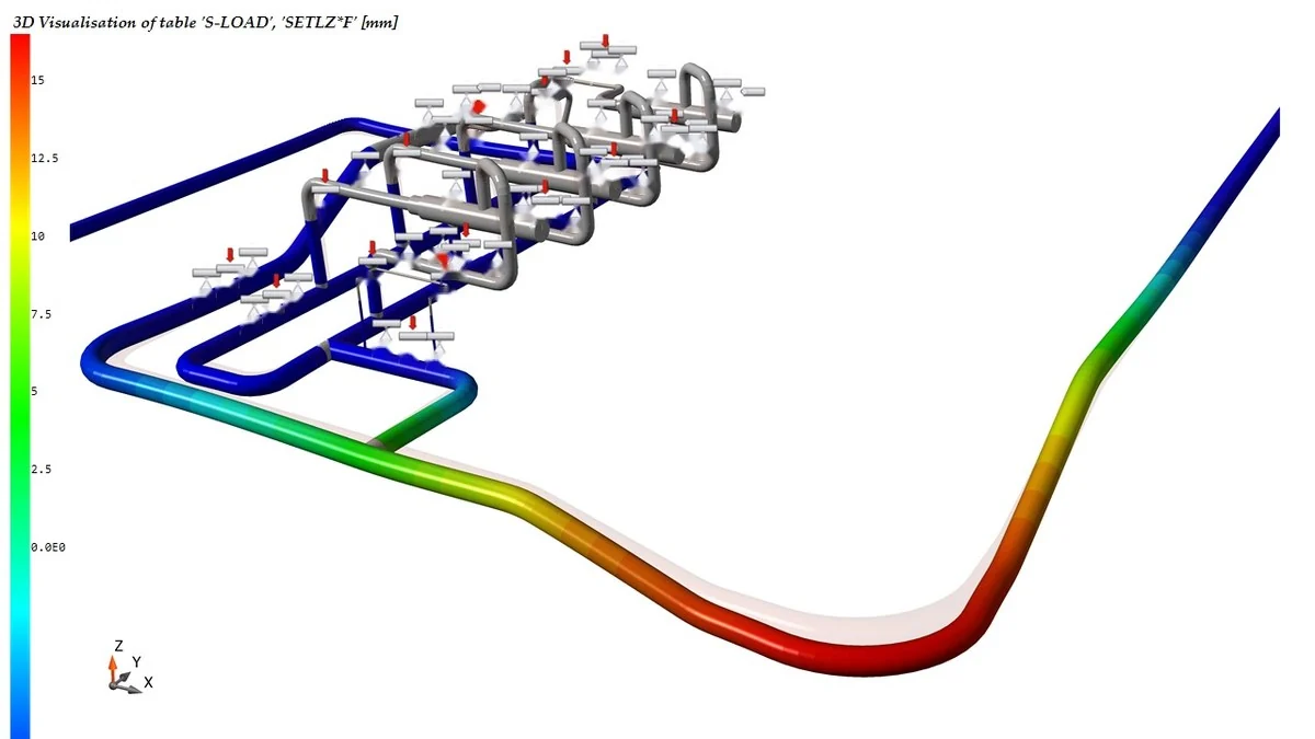
Figure 4 shows the 3D visualisation of the S-LOAD table, column SETLZ*F (mm), along the route: the applied settlement can be read directly on the colour scale, with a maximum of the order of 15 mm, consistent with 10 mm × 1.5.
What I check in the model
- I do not replace a distributed settlement with an imposed displacement at a few nodes.
- I read LENGTH as half a wavelength: in Double the whole bowl is 2·LENGTH long.
- I remember that SUBZMAX is multiplied by UNCF (default 1.5): the geotechnical value must not already be factored.
- I compare ℓ with the characteristic length 1/λ before choosing the shape.
- With Right or Left I read the results at the jump at X-P with particular care.
- I keep the construction settlement fv and the settlement difference Δz separate (NEN 3650-2, Annex A).
- I check that soil reactions stay within bearing capacity and passive pressure, and I check catenary tension in restrained sections.
Limits. The formulas describe the reference behaviour of the beam and of the sinusoidal half wave; the result depends on the soil interaction model and on the limits of the applied code, and must be read in the context of the individual project.
References
- NEN 3650-1:2020, Annex C.4.1.2 and C.4.1.3.
- NEN 3650-2:2020, Annex A.
- PLE documentation: Vertical soil subsidence [SUBSIDE] and Data description/conditions.